The structural analysis software RFEM 6 is the basis of a modular software system. The main program RFEM 6 is used to define structures, materials, and loads of planar and spatial structural systems consisting of plates, walls, shells, and members. The program also allows you to create combined structures as well as to model solid and contact elements.
RSTAB 9 is a powerful analysis and design software for 3D beam, frame, or truss structure calculations, reflecting the current state of the art and helping structural engineers meet requirements in modern civil engineering.
Do you often spend too long calculating cross-sections? Dlubal Software and the RSECTION stand-alone program facilitate your work by determining section properties of various cross-sections and performing a subsequent stress analysis.
Do you always know where the wind is blowing from? From the direction of innovation, of course! With RWIND 2, you have a program at your side that uses a digital wind tunnel for the numerical simulation of wind flows. The program simulates these flows around any building geometry and determines the wind loads on the surfaces.
Are you looking for an overview of snow load zones, wind zones, and seismic zones? Then you are in the right place. Use the Geo-Zone Tool to determine quickly and efficiently snow loads, wind speeds, and seismic data according to ASCE 7‑16 and other international standards.
Would you like to try out the capabilities of the Dlubal Software programs? You have the opportunity to do so! The free 90-day full version allows you to thoroughly test all our programs.
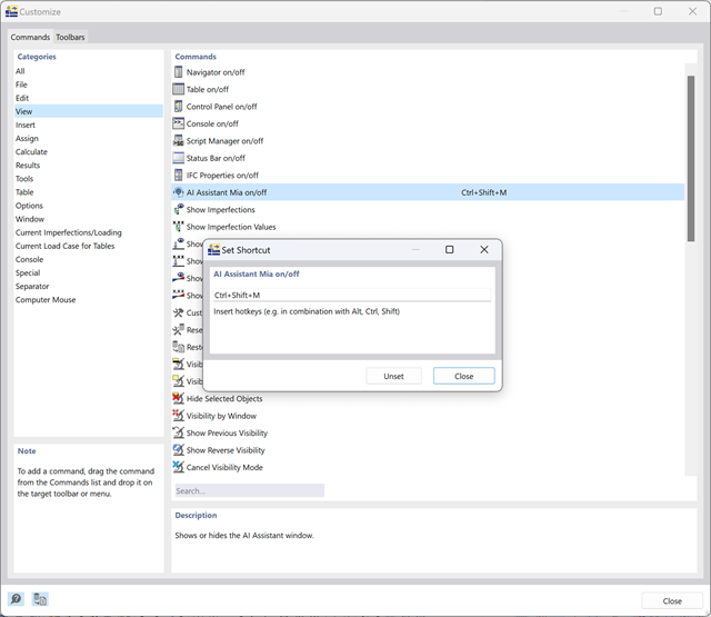
In RFEM 6 and RSTAB 8, you can freely set all keyboard shortcuts.
To do this, open the "Customize" dialog box using the menu "Options > Customize Menus and Toolbars".
Click "View" in the "Categories" list on the left, then double-click "AI Assistant Mia on/off" in the "Commands" list on the right.Here you can define a new keyboard shortcut.
Saving Graphic Template
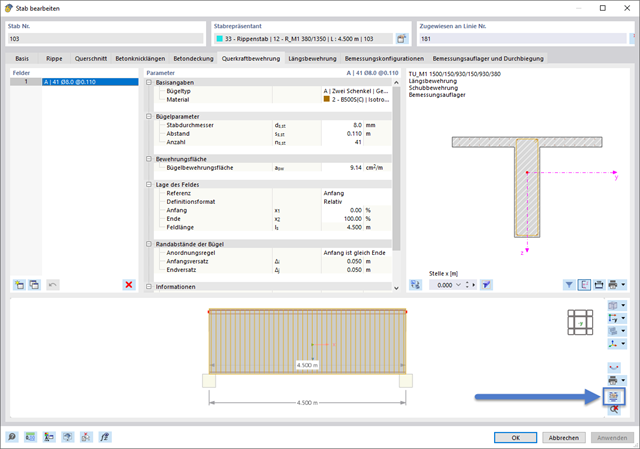
Once you have assigned the concrete material and activated the design properties in the member input dialog box, the display of the reinforcement layout for the selected member is available.
In the Display Reinforcement Layout window, you can proceed as follows. 1. Use the options in the menu bar to customize the display according to your preferences. 2. This configuration can send "Directly to a printer" as a template.3. When saving the template, it is stored globally and is also available for future models.
Multi Print of Reinforcement Layout for Selected Members
Use this graphic template to print the reinforcement of any members with a similarly formatted reinforcement layout in a multi print.
You can access the requently used functions and commands in the program by using the integrated keyboard functions (shortcuts). For example, to print a graphic, the corresponding keyboard shortcut is [Ctrl]+[V]. Some important keyboard functions are listed in Chapter Keyboard Functions of the RFEM 5 manual.
If you want to assign user-defined shortcuts in RFEM 6 or RSTAB 9, proceed as follows:
Please note that some key combinations may already be used by the operating system for other functions. Make sure that the combination you select does not conflict with any existing shortcut.
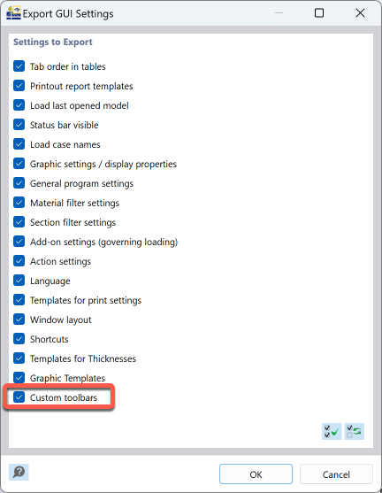
Click the menu item "Options → Export GUI Settings...".
You can select whether you want to only save the settings of the toolbars or also other elements. After clicking the OK button, you will be asked to enter the name of the file.
Now, transfer the file to the other computer. Import the file by selecting the menu item "Options → Import GUI Settings..." and importing the file.
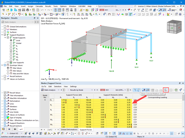
Yes, it is.To deactivate the blue/red colors in the result tables, click the "View" menu of the tables, and press the "Display Color Scale" button. You can also use the corresponding button in the table toolbar.
For the printout report, you can also deactivate the "Color Scale" option in the "Printer and Page Settings" dialog box in the "Other Settings" tab.
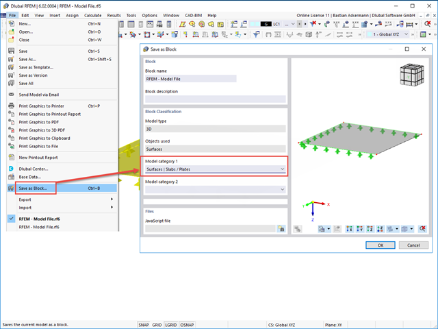
A block is initially saved as in RFEM 5 / RSTAB 8, and imported via Dlubal Center:
1) Select the objects to be saved.
2) Menu "File", "Save as Block", please note: Enter the model category; see Image 01.
3) In the target file, open Dlubal Center via the "File" menu or the toolbar and open the block in the corresponding model category; see Image 02.
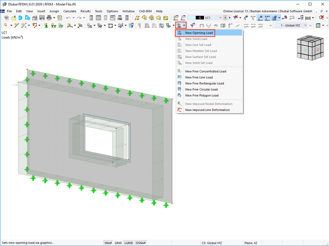
To do this, there is the opening load that you can define either via the menu bar (→ Insert → Loads → Opening Loads) or via the toolbar (drop-down menu for special loads; see the image).
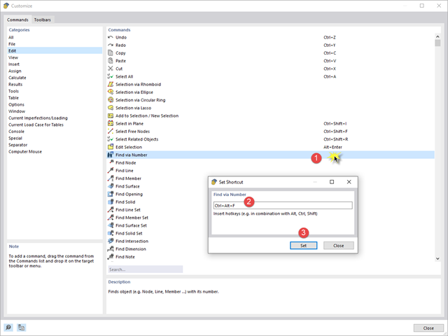
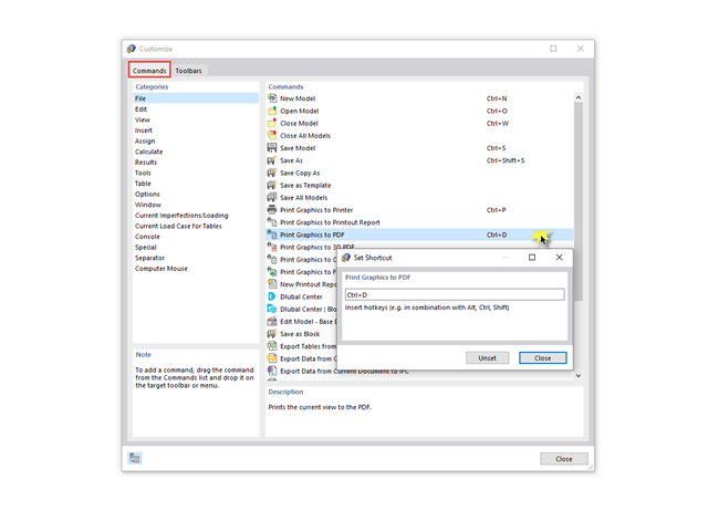
For RFEM 6 and RSTAB 9, it is possible to assign hotkeys to a wide range of commands. This way, you can quickly and easily execute frequently used commands with a previously assigned key combination.
In the Options menu, select the Customize Menus and Toolbars function. In the "Customize" dialog box, you can change or add the hotkeys.
Tip: This also works for your computer mouse: If it has other buttons in addition to the left, right, and middle buttons, you can assign a hotkey to them.
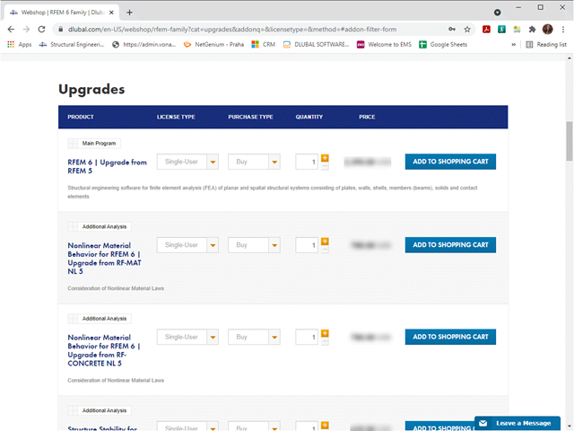
To upgrade from RFEM 5 to RFEM 6 or RSTAB 8 to RSTAB 9 will require an upgrade fee which is not covered under your existing RFEM 5 / RSTAB 8 Basic or Pro Service Contract.
Visit the webshop to learn more about upgrade options or contact our sales team today for your customized quote.
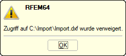
The transfer of internal forces from RFEM or RSTAB into SHAPE‑THIN is only possible with administrator rights. Unfortunately, it is not possible to grant access only to certain folders, for example, as this process deeply affects the operating system.
However, it is also possible in SHAPE‑THIN to import ithe internal forces from RFEM/RSTAB without using the "Import Results from RFEM/RSTAB" function. The following options are available:
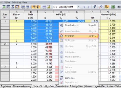
Inserting Internal Forces via Clipboard
Inserting Internal Forces via Excel
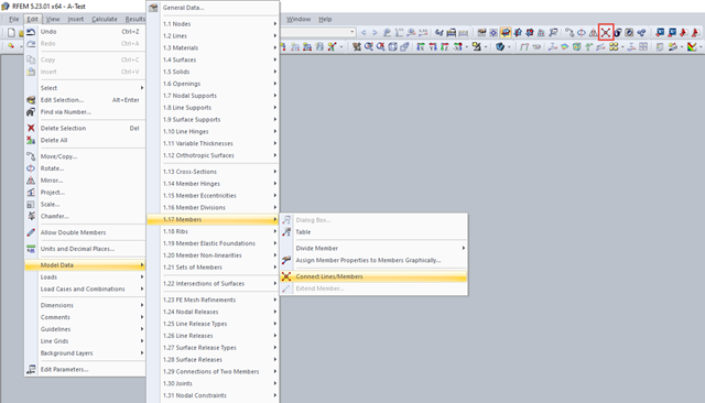
The function you are looking for is "Connect Lines/Members". You can use this by selecting the menu item Edit → Model Data → Members → "Connect Lines/Members" or using the corresponding toolbar button (see Image 01).
After activating the command, a window is opened via the connection point. A node is created between the intersecting members.
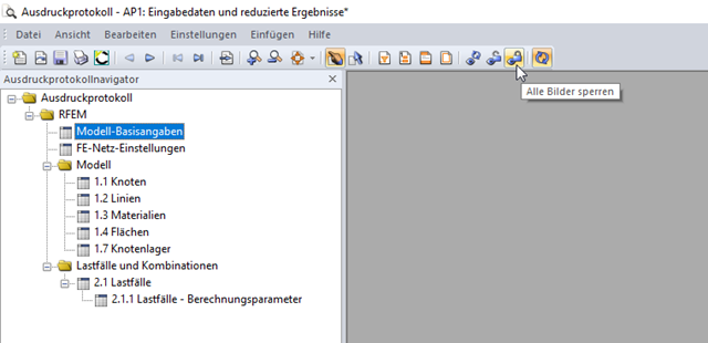
In the tabs Model Data, Load Cases and Combinations, Loads, and Results, you can select the corresponding tables in the "Tables to Display" dialog section (Image 04).
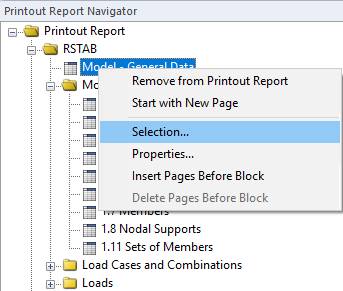
Furthermore, you can delete the chapters in the opened printout report by using the shortcut menu. To do this, select the corresponding chapters and then select the "Remove from Printout Report" option in the shortcut menu (Image 05). To add the chapter(s), use the "Printout Report Selection" dialog box.
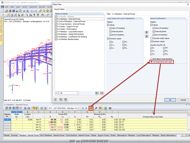
The corresponding load cases and load combinations can be displayed in result tables. For this, select the "Corresponding Load Cases" option in the "Table Filter" dialog box (Image 01). To open the dialog box, use the menu Table → View → Result Filter or the corresponding button in the table toolbar (Image 01).
In RSTAB, the corresponding load cases/combinations can be displayed in the following tables:
In RFEM, the corresponding load cases/combinations can be displayed in the following tables:
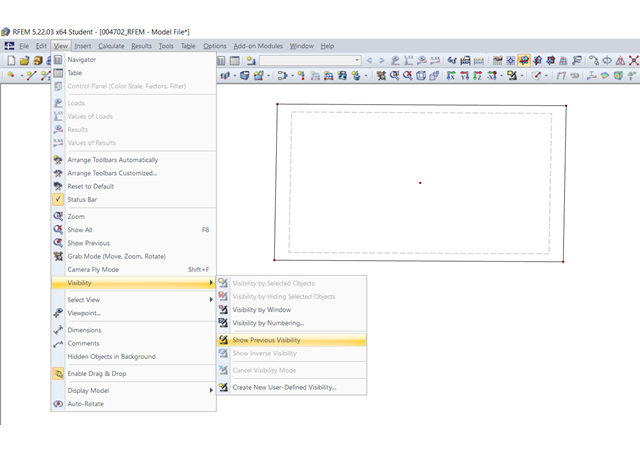
If all other nodes are displayed, the visibility mode is probably activated. Deactivate it using the toolbar or the menu bar; see Image 01.
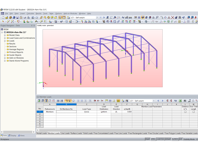
To apply a member load (graphically) in RFEM 5 or RSTAB 8, open the "New Member Load" dialog box using the menu Insert → Loads → 3.2 Member Loads → Graphically, or using the corresponding icon in the toolbar. Then, define the load parameters. After clicking "OK", you can apply the member load to the respective member. As an alternative, it is possible to apply member loads to several members in a single step. To do this, hold down the left mouse button and draw a window over the relevant members (Image 01). If you draw the window from left to right, the load is applied to the members that rest completely in this area. If you draw the window from right to left, the load is also applied to the members that are only partially in this area. This is also useful when working with visibilities or views.
Furthermore, it is also possible to first select the members to which the member load is to be applied, then open the "New Member Load" dialog box. After defining the member load parameters and clicking "OK", the member load is applied to the previously selected members.
The video shows in Load Case 1 how a member load is applied by clicking the respective members one after another. In Load Case 2, the load is applied in a single step by drawing a window over the relevant members. In Load Case 3, the members to be loaded are selected first. After defining the member load parameters, the member load is applied to the previously selected members.
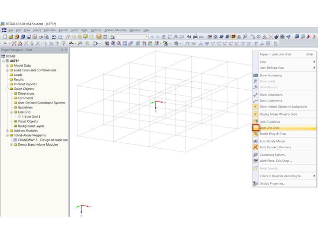
First, make sure that the line grid is not locked. To do this, right-click in an empty area of the work window. If the line grid is not locked, there is no check mark in front of the "Lock Line Grids" entry (Image 01). If this check box is selected, left-click the "Lock Line Grids" entry (Image 02).
You can then copy the line grid using the "Move or Copy" function. To do this, select the line grid first. Then, open the "Move or Copy" dialog box using the menu Edit → Move/Copy or using the corresponding button in the toolbar. Then, define the number of copies and the displacement vector (Image 03).
As an alternative, you can copy a line grid using drag & drop. First, make sure that the "Enable Drag & Drop" function is activated. To do this, right-click in an empty area of the work window. The "Enable Drag & Drop" option must be activated in the shortcut menu (Image 04).
Left-click the line grid to select and drag it to the desired location while holding down the left mouse button and the Ctrl key. As soon as you release the mouse button, the copy is created at the location.
The video shows how to copy a line grid using the "Move or Copy" function. Subsequently, it shows how to copy using Drag & Drop.
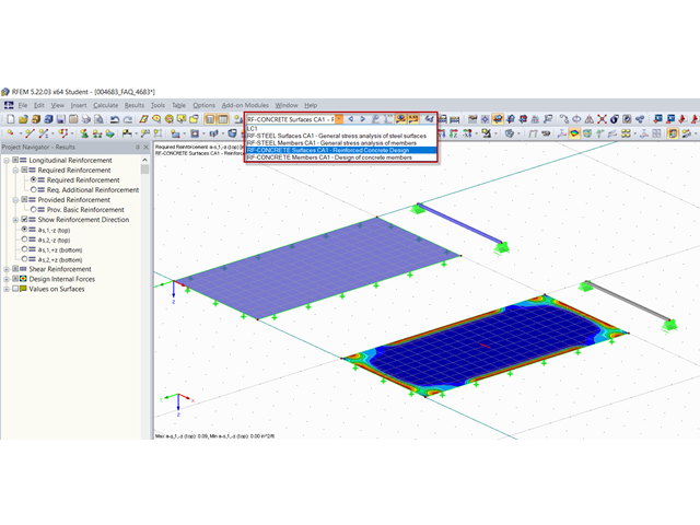
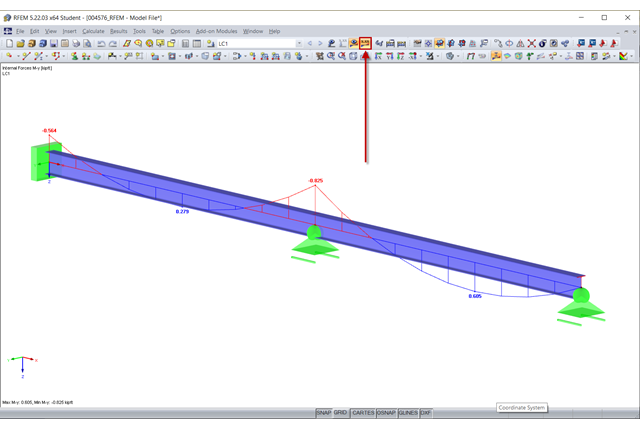
The results of most add-on modules can be displayed easily in the graphic of the main program. There are two options for this:
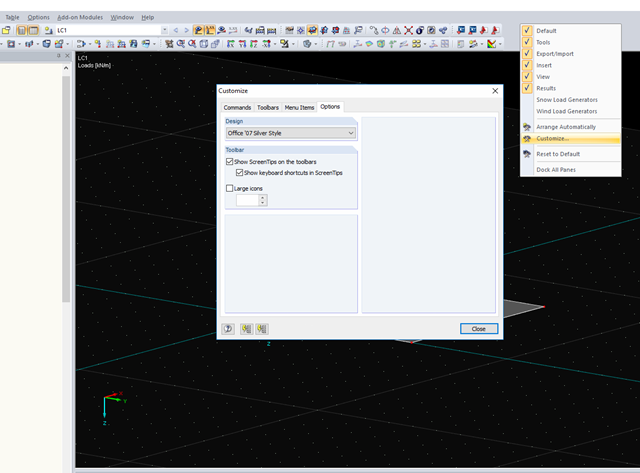
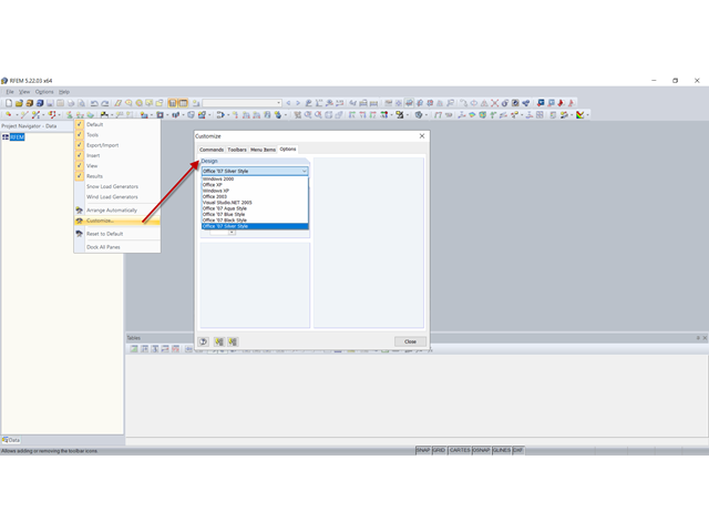
Right-click in the toolbar area and select "Customize".
In the "Options" tab, you can now select your preferred appearance of the program interface.
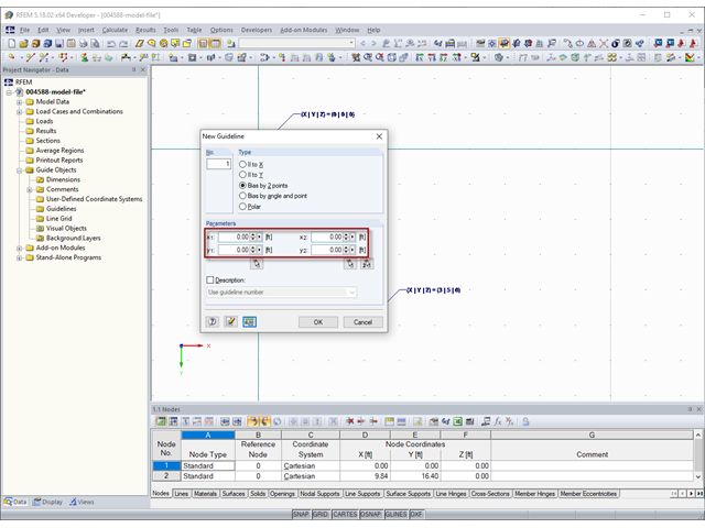
The coordinates of guidelines (Image 01) to be specified in the "New Guideline" dialog box under "Parameters" refer to the zero point of the work plane.
You can set the zero point of the work plane in the "Work Plane and Grid/Snap" dialog box (Image 02) using the menu Tools→ Select Work Plane → Set Origin or the corresponding button in the toolbar.
In the video, the zero point of the work plane is set to the coordinates X = 3 m, Y = 5 m, and Z = 0 m. Then, a guideline is created parallel to X (|| to X) with the coordinate y1 = 0 m. Thus, the guideline is in the global coordinate system at Y = 5 m.
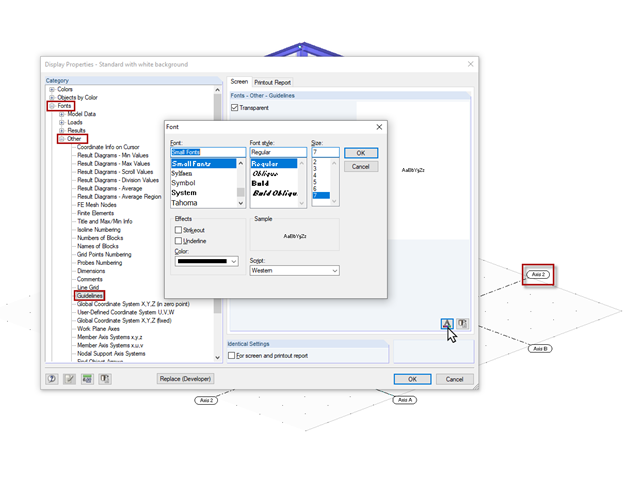
You can find this setting in Display Properties under the "Font", "Other", and "Guidelines" categories.
There are two ways to display result values:
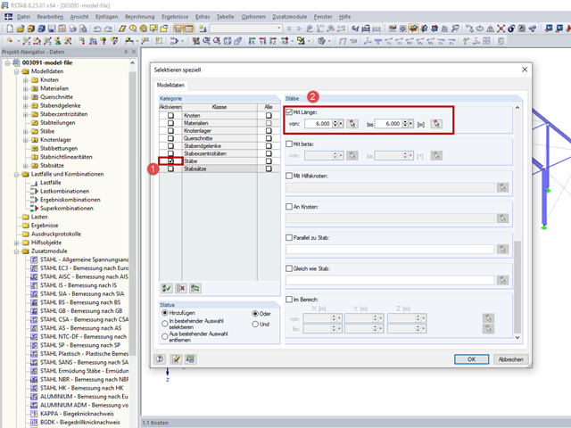
The "Special Selection" function allows you to select objects with specific properties. To open the Special Selection dialog box, use the menu Edit → Select → Special or the corresponding toolbar button.
In the "Special Selection" dialog box, select the "Members" category and activate the "With length" check box. The length range can then be entered in the "from" and "to" text boxes. Use the "Select Member and Import Properties" button to import the member length (Image 01).
The video first shows how to select members that correspond to the length of a particular member. Furthermore, it shows how to select members that lie within a certain length range.
Dlubal Software has a modular structure, so you can customize the software individually. In any case, you need the main program. This is either RSTAB (for frame & truss structures), or RFEM (for general finite element calculations of beam structures, surfaces, and solid elements). Furthermore, you can configure the add-ons that you need, depending on your task.
We will be happy to advise you on possible program combinations. Thus, you can customize the add-ons to your specific needs. If necessary, you can quickly order the program components that you did not need before.
The first step is often to familiarize yourself with the trial version or watch some short videos. Check our website to find solution for various application areas.
We will be happy to advise you in detail and without obligation. Give us a call or send us an email. We'll be happy to assist you.
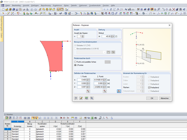
A solid of revolution can be created using the "Rotate" function. First, select the surface to be rotated, then open the "Rotate - Copy" dialog box by clicking the "Edit → Rotate" in the menu, the shortcut menu of the object, or the corresponding toolbar button. In the "Rotate - Copy" dialog box (Image 01), you must then define the number of copies as one. Furthermore, you can specify the desired angle of rotation and the axis of rotation.
In the "Detail Settings for Move/Rotate/Mirror" dialog box, which you can open by clicking the "Edit Expanded Settings" button, select the "Create new solid bodies between the selected surfaces and their copies" check box (Image 02).
After clicking [OK], the solid is created (Image 03).
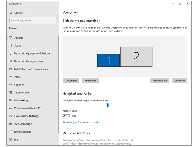
If you use two or more monitors, you can, for example, move the project navigator, tables, the add-on module windows, or a printout report to the other display. This way, you can easily enlarge the workspace of the model.
By clicking the link below, you can find instructions on how to customize the elements of the user interface.
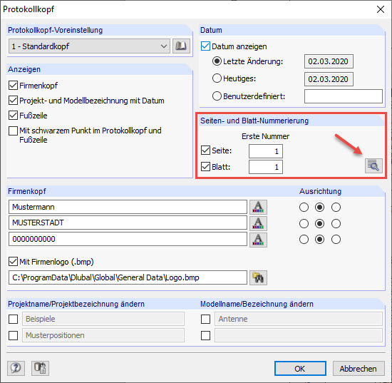
The header properties created from the customer data during the installation can be changed in the printout report using the menu Settings → Header... or using the corresponding button in the toolbar of the printout report.
For example, if you set the default numbers for "Page" and select the check box, the individual pages are managed continuously.
The "Details" button allows you to enter detailed settings for the numbering in a new dialog box. Among other things, this dialog box controls whether a prefix is added to the page numbering. The prefix can be an abbreviation that is specified chapter by chapter, for example, to indicate all model data in the numbering with the prefix "MO".
Unfortunately, it is not possible to add suffixes.